Advanced 7 Segment Display Driver with a 4511 IC and Raspberry Pi

Background
In my first post of this series I discussed a very simple way of driving a 7 segment display directly through the Raspberry Pi 2. Whilst this does word, in practice it has a number of caveats and limitations. Firstly the current through each LED is limited to what can be provided by each GPIO pin on the Raspberry Pi. Secondly, if all segments are lit, then the cumulative current going into a GPIO input pin exceeds the recommended input current. Whilst I have no doubt the Raspberry Pi can handle it, I would not recommend it for long term usage.
Source code available on Github
Introduction
To improve on the previous post and drive a seven segment display in a more effective way, I will make two significant changes. Firstly I will use a CMOS4511 integrated circuit chip to drive the 7 segment display from a binary input. Secondly, to protect the GPIO input transistors will be used to switch the displays on and off and the circuit will sink to ground rather than the GPIO pins.
Pre-Requisites
1 x Raspberry Pi 2
1 x Cmos 4511 IC
4 x NPN Transistors (more or less depending on number of digits on display)
1 x 5641AS 7 segment display (Or similar 7 segment display)
7 x 220 Ohm Resistor
4 x 1 kOhm Resistor (Same number as transistors)
Fritzing
Circuit
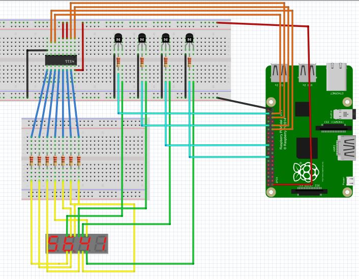
The above fritzing diagram displays the complete circuit used in the demonstration. Different GPIO pins can be used if desirable for output to both the 4511 and the GPIO.
The CMOS4511 IC is used to convert a binary input to a 7 segment display output. The pin-out for the 4511 can be found on the datasheet. The 4 inputs D0 – D3 are connected to the Raspberry Pi, and the 7 outputs a to g are connected to the corresponding segments on the display via 220 Ohm resistors.Vcc, BL and LT should all be connected to the power source [recommended 3.3v] and ground should be connected to ground. LE can be left unconnected.
From the display, each digit display pin should be connected to the collector of an NPN transistor, and each transistor emitter can be connected to ground. Each transistor base can be connected to a GPIO pin via a 1 kOhm resistor.
Code
As the core code will be identical to the previous driver then it makes sense to abstract our new driver from the previous code. To do this we need to make a few small changes.
Firstly as we’re going to use 4 pins rather than 7 to drive our display, we need to override the SetDisplay method in our existing class, so this should now be set to virtual to allow us to do this.We will also need to override the ClearDisplay() method so this is also set as virtual.
On top of this, as we’re using a different set of GPIO pins, we need to be able to provide a different constructor, but as we don’t want to use the original base constructor, we must provide another, in this case parameter-less constructor. As we only want derived classes to be able to use this, we can set the constructor as protected. We can also take advantage of this constructor to set up the cancellation tokens that were previously set in the main constructor, preventing the need to provide protected accessors to these fields.
protected Display()
{
  this.cts = new CancellationTokenSource();
  this.token = new CancellationToken();
}
The final thing we need to do to our original class is to make the displays array accessible to derived classes
protected GpioPin\[\] Displays
        {
            get
            {
                return this.displays;
            }
            set
            {
                this.displays = value;
            }
        }
Now we’re ready to create our new derived class. A new constructor similar to our original base class should be created but we only need to provide 4 output pins [for the 4511 D0-D3] and then our display pins. The initialisation of the pins is then carried out as per the base class.
Next we can provide the overridden SetDisplay method. Instead of converting the supplied int to it’s 7 segment representation, this version converts the supplied in to it’s binary representation.
protected override void SetDisplay(GpioPin displayPin, int value)
        {
            this.ClearDisplay();
            switch (value)
            {
                case 0:
                    this.SetLow(new GpioPin\[\] { this.pinBcd0, this.pinBcd1, this.pinBcd2, this.pinBcd3 });
                    break;
                case 1:
                    this.SetHigh(new GpioPin\[\] { this.pinBcd0 });
                    this.SetLow(new GpioPin\[\] { this.pinBcd1, this.pinBcd2, this.pinBcd3 });
                    break;
                case 2:
                    this.SetHigh(new GpioPin\[\] { this.pinBcd1 });
                    this.SetLow(new GpioPin\[\] { this.pinBcd0, this.pinBcd2, this.pinBcd3 });
                    break;
                case 3:
                    this.SetHigh(new GpioPin\[\] { this.pinBcd0, this.pinBcd1 });
                    this.SetLow(new GpioPin\[\] { this.pinBcd2, this.pinBcd3 });
                    break;
                case 4:
                    this.SetHigh(new GpioPin\[\] { this.pinBcd2 });
                    this.SetLow(new GpioPin\[\] { this.pinBcd0, this.pinBcd1, this.pinBcd3 });
                    break;
                case 5:
                    this.SetHigh(new GpioPin\[\] { this.pinBcd0, this.pinBcd2 });
                    this.SetLow(new GpioPin\[\] { this.pinBcd1,this.pinBcd3 });
                    break;
                case 6:
                    this.SetHigh(new GpioPin\[\] { this.pinBcd1, this.pinBcd2});
                    this.SetLow(new GpioPin\[\] { this.pinBcd0, this.pinBcd3 });
                    break;
                case 7:
                    this.SetHigh(new GpioPin\[\] { this.pinBcd0, this.pinBcd1, this.pinBcd2 });
                    this.SetLow(new GpioPin\[\] { this.pinBcd3 });
                    break;
                case 8:
                    this.SetHigh(new GpioPin\[\] { this.pinBcd3 });
                    this.SetLow(new GpioPin\[\] { this.pinBcd0, this.pinBcd1, this.pinBcd2 });
                    break;
                case 9:
                    this.SetHigh(new GpioPin\[\] { this.pinBcd0, this.pinBcd3 });
                    this.SetLow(new GpioPin\[\] { this.pinBcd1, this.pinBcd2 });
                    break;
                case 10:  // Clear Display
                    this.SetHigh(new GpioPin\[\] { this.pinBcd0, this.pinBcd1, this.pinBcd2, this.pinBcd3 });
                    break;
                default:
                    this.SetHigh(new GpioPin\[\] { this.pinBcd0, this.pinBcd1, this.pinBcd2, this.pinBcd3 });
                    break;
            }
            this.SetHigh(new GpioPin\[\] { displayPin });
        }
There is one other change in this method. That is that instead of setting the GPIO pin low to turn the display digit on, this time we set the GPIO high. This is because instead of turning the pin low to allow current to sink into the GPIO pin, we now turn set the pin high which then ‘switches’ the transistor which allows current to flow and sink to the ground rail. It is for this reason we also override the ClearDisplays method to set all GPIO pins low [instead of high].
protected override void ClearDisplay()
{
  this.SetLow(this.Displays);
}
Video
The below video shows the project in action
The post [RPi Series] Advanced 7 Segment Display Driver with a 4511 IC appeared first on Talking I.T. Through.